
How to Build a Calculator in Unity
Part 1 – Design
Introduction
This is a multi-part tutorial focused on designing, building, and deploying a basic calculator in Unity. While Unity is probably not the best tool to use to build a calculator, it will certainly get you more familiar with the engine and help you practice designing functionality before implementing the code.
About
- Subjects: Unity, Software Development, and UML
- Objective: The purpose of this tutorial is to walk you through how to design the functionality of software before implementing it.
- Time Allotment: 45 min
Getting Started
Define the Requirements
So, we have decided we want to build a calculator. Great, now what do you want your calculator to do? Do you want it to do just basic addition and subtraction? What about multiplying and dividing? Ok, so what about exponents, parenthesis, square root, decimals? These are all things you should be thinking about BEFORE you start building your software. To help us keep up with our decisions we should start writing our requirements down. Let us call these requirements “features”.
- Features:
- Addition
- Subtract
- Multiply
- Divide
- Exponents
- Parenthesis
- Percentage
- Positive/Negative
- Pi
- Equals
Our list is looking good now. We know what calculations we want our calculator to perform. Are there any other features we need? Well, obviously we need numbers for the user to press. So, let us move our calculations under the header calculations and define what UI features we need.
- Features:
- Calculations:
- Addition
- Subtract
- Multiply
- Divide
- Exponents
- Parenthesis
- Percentage
- Positive/Negative
- Pi
- Equals
- UI:
- Buttons (0-9 and operations)
- Display for current input
- Display for the current equation
- Calculations:
Now, we have buttons to press, a display to show what we entered, and a display for showing the current calculation we are working on.
You may be thinking at this point, “This is a calculator, everyone knows what a calculator does. Why do I need all this?” and the answer to that is simple. By thinking about and laying out your requirements, no matter how obvious they may be, you are beginning to build a mental model of your application. Listing requirements lead to user stories about what the user will do and see, which again leads to developing data flow/ logic maps. This will ultimately lead to a better overall design that can be easier to implement, maintain, and extend in the future.
Develop User Stories
User stories are essential for figuring out what you want the user to see and how they will interact with your software. These do not have to be extremely detailed and if you find yourself writing a confusing story then it is best to break it down into its smaller parts. Using our list of requirements, we can begin defining that interaction.
User Story 1: User clicks a button, and that value is then added to the display.
Simple but there are some concerns. What if the user hits an operator button but has not entered a number to operate on? What if the user hits the equals button but there is no operator or no equation to evaluate with? Let us break up this store and better define it.
User Story 1: User clicks a number button, and that value is then added to the display. If the previous button entered was an operator then the operator is added to the equation and the display is cleared only showing the new number. If the previous button was a number or a decimal the number is appended to the end of the display text.
User Story 2: User clicks an operator button, and that value is then added to the display. If the display text is empty then the previous value will be assumed to be zero which will be added to the equation and the operator is added to the display. If the operator is a decimal and there are no other decimals in the display text then it is appended to the display text. If the previous value was another operator, excluding the decimal point, then the display text is changed to the new operator. If the previous button was a number then the number is added to the equation and the operator will be added to the display.
User Story 3: User clicks the equals button. The display text is added to the equation and the equation is evaluated. The result is added to the display.
This is looking pretty good so far. There are three types of input a user can select and there are three stories that show what the user should expect. Now we can work what we have into diagrams.
Creating Class Diagrams
For creating diagrams, I recommend this great resource, diagrams.net formally draw.io. This is an open-source project that has a web app for creating diagrams as well as integrations for google (docs, sheets, slides), Office 365 (Word, Excel, PowerPoint), VSCode, and many more.
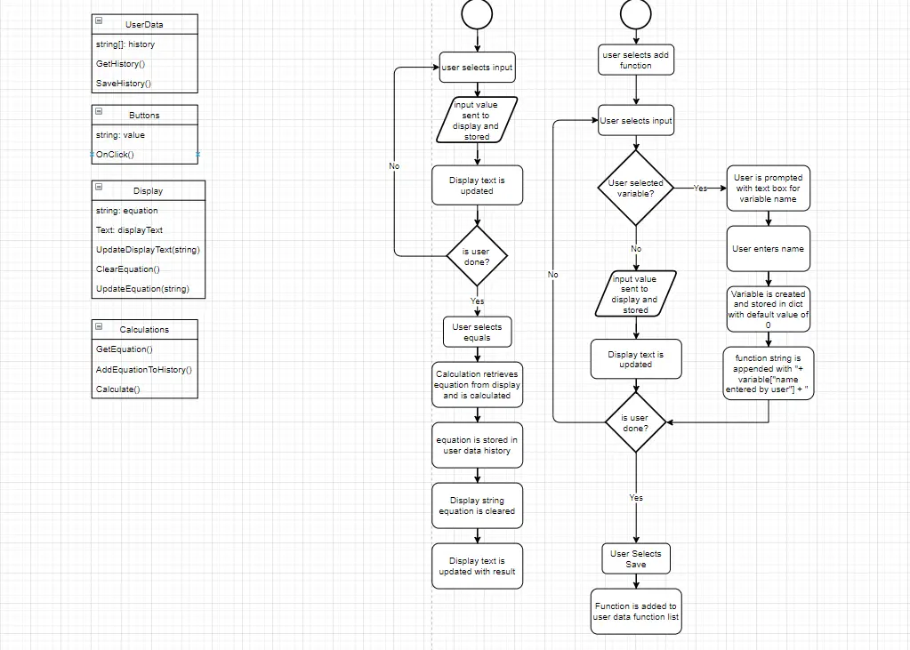
Using our requirements and user stories as a guide we can begin building up our classes. We know we need buttons so let us start there.
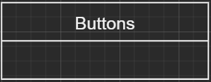
Now that we have that what do our buttons need? They need to have some type of value, 0-9, +, -, etc. So, let us create a type of string called value. After that we need something to happen when we click the button. Let us call this method AddValueToDisplay(). Now our class should look like this:
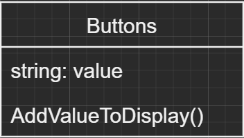
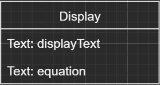
Next, we know we need a display to show our input.
What does our display need to hold? Again, going back to the user stories and requirements we need to have a place to store the display and equation text. Unity displays text inside the Text component so let us create one for each of our displays.
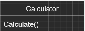
Finally, we need a way to perform calculations but that does not seem to fall into the role of the other two classes so let us create a new class called Calculator. This class only needs one method we will call Calculate() that will handle all of our calculations.
Create the Logic Flow
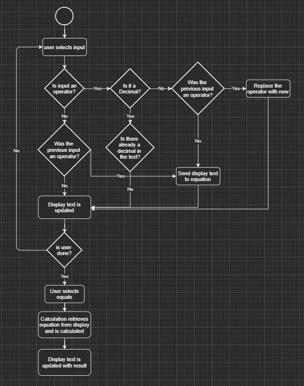
Visualizing the flow of data can help with determining what needs to happen in the code. This is especially so when you have a more complex process occurring. Here we can see the start of the operation represented by the circle. Once the calculator has started the user can then supply input. For the logic flow we need to build out what happens when the user provides input. We have already specified what it looks like for the user in the user story but here imagine what it looks like for the data being provided. For this diagram we kept the design simple. Diamond shapes represent if statements and the rounded rectangles represent actions that occur.
We now have a plan of attack for building everything out in Unity. Next, check out How to Build a Calculator in Unity Part 2 where we will start creating our calculator in Unity. Also, we currently have two games on Google Play and at the Amazon Appstore for Android, check them out below.